|
|
|
| |
|
| |
|
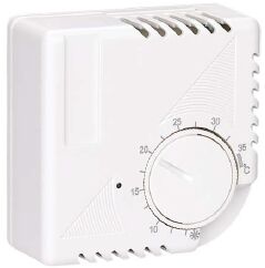
| MECHANICAL THERMOSTAT |
| |
|
|
SP7000 |
| Features |
| |
| Use Instructions Room Thermostat |
| |
| Bimetallic room thermostat for heating and air-conditioning installations Thermal, electrical and mechanical features |
| Breaking capacity on opening contact,10A-250V A.C.(ohmic load) Differential: 0.5K. |
| |
| |
| |
| |
| |
|
|
|
|
| |
|
|
Temperature's Scale Adjustment |
| |
| After almost two days from the installation, to obtain a precise scale adjustment, measure the room temperature with a |
| reference thermometer, placed aside the thermostat, holding the shagreened part of the knob, turn the index with a coin, |
| to reach the same value of the thermometer, We suggest to install the equipment at about 1.5mt from the floor and far |
| from any heat source. |
| |
| |
| Parts |
| |
| ①Base. |
| ②Cover. |
| ③Cover screw. |
| ④Knob Lockpins, The lock pins for scale limitation. |
| ⑤Are to be derached from the base of the thermostat. They are Located on the fixing holes. |
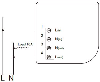
SP7000A WIRING |
⑥Index:The fixing of the room thermostat can be done directly on the wall by screws and nags. |
| |
|
|
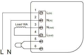
B1-With N.C. contact. |
| B2-With N.C. contact and ON-OFF switch. |
| B3-With SPDT contact(change-over). |
| B4-With change-over contact(SPDT) and ON-OFF switch. |
| B7-With nomally closed contact on “Winter”and normally opencontact on“Summer”plus “Summer-Winter” selector- |
| switch. |
| |
| |
| |
| |
| |
| |
SP7000B WIRING |
|
| |
| IMPORTANT |
| |
| ①Accelerating resistance with voltage to 220-250V a.c. |
| ②This thermostat is provided with an accelerating resistance which mustbe absolutely connected in onder to obtain the regulations performances. |
| ③The terminal 4has thus to be connected to the neutral according to the diagram shown on the cover. |
| ④This connection allows also the working of the pilot lamp which indicates the operation of the heating. |
| |
| |